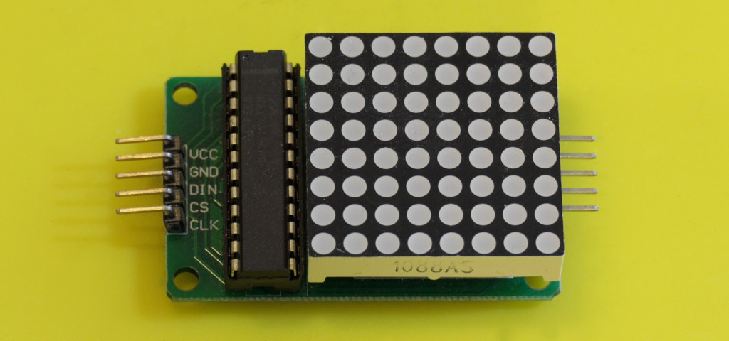
An 8×8 matrix can communicate “ready”, “attention”, or a rough level at a glance. The useful design challenge is to make the meaning obvious without depending only on color or a decorative animation. Here we alternate a check mark and an exclamation mark.
Connect one module
| Connection | Destination or purpose |
|---|---|
| VCC / GND | 5 V / GND for one module at low intensity. |
| DIN | D7. |
| CLK | D5. |
| CS or LOAD | D6. |
| DOUT connector | Leave unused. |
Use the input end of the module. Check its current-setting resistor and bypass capacitors against its documentation. This example starts at low intensity with sparse symbols. Several modules or a bright all-pixels display need a separately sized supply with common ground.
Install LedControl
Install LedControl through Library Manager. This example uses that library consistently; similarly named matrix libraries have different APIs.
Download the complete Arduino sketch
#include <LedControl.h>
const byte dinPin = 7, clockPin = 5, loadPin = 6;
LedControl display(dinPin, clockPin, loadPin, 1);
const byte ok[8] = {0x00, 0x01, 0x03, 0x86, 0xCC, 0x78, 0x30, 0x00};
const byte attention[8] = {0x18, 0x18, 0x18, 0x18, 0x18, 0x00, 0x18, 0x00};
unsigned long changedAt = 0;
bool showingOk = true;

void draw(const byte *rows) {
  for (byte row = 0; row < 8; ++row) display.setRow(0, row, rows[row]);
}

void setup() {
  display.shutdown(0, false);
  display.setIntensity(0, 1);
  display.clearDisplay(0);
  draw(ok);
}

void loop() {
  if (millis() - changedAt >= 2000) {
    changedAt = millis(); showingOk = !showingOk;
    draw(showingOk ? ok : attention);
  }
}
The display should alternate symbols every two seconds. If they are mirrored or rotated, your module connects rows and columns in a different orientation. Establish the orientation by lighting one pixel and then one row before changing a whole character set.
Understand the bitmap
Each byte represents eight pixels in a row. For example, 0x18 is binary 00011000, so the two center pixels are lit. Eight bytes define one symbol. Two symbols are small enough to keep the example straightforward; a large font collection may belong in flash memory on a memory-limited Uno.
The MAX7219 handles scanning and brightness while your program updates its display memory. The library sends data over a clocked serial interface. An arbitrary number of chained panels is not free: each needs power, more update traffic, and enough physical wiring quality.
Troubleshooting
- Blank screen: check that the module is powered, connected at DIN, and taken out of shutdown.
- Random patterns: check LOAD versus CLK, common ground, and short wiring.
- Works with Uno but not ESP32: a MAX7219 running at 5 V does not guarantee that a 3.3 V signal reaches its specified HIGH threshold. Use suitable logic translation.
- Controller resets at higher brightness: reduce load and correct the power arrangement.
Replace the timed alternation with a real sensor state, and label the enclosure so the symbols have a clear meaning. Show a distinct “no reading” pattern rather than implying everything is fine when data stops. See MAX7219 documentation and the LedControl project.