
A shift register is a simple memory device that allows data to be "shifted" bit-by-bit into or out of the register.
What are shift registers used for?
One place you might use a shift register is to control up to eight components, such as LEDs, using only three Arduino pins instead of a separate pin for each LED. Moreover, some shift registers can be chained together to expose a huge number of inputs or outputs while using only a few pins on the microcontroller. Shift registers are also used for controlling 7-segment LCD displays and various other components.
The shift register is also used as a small region of memory to store arbitrary data, just like the similarly named "registers" in a CPU. If you're building a circuit that has the concept of "current state" that can be represented by a small number of bits, a shift register can simplify the circuit compared to implementing that state using individual flip-flops.
An eight-pin DIP switch is often paired with an eight-bit shift register that will read the eight switches in parallel and convert their state to eight bits that are read in series by a microcontroller. This type of shift register is called "parallel in, serial out". A common model is the 74HC165.
The common 74HC595 shift register
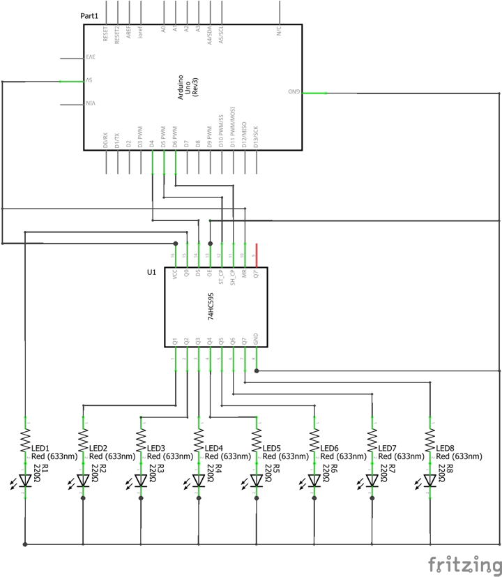
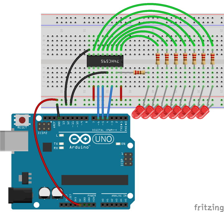
Another common shift register for Arduino projects is the 74HC595. The 74HC595 is a "serial in, parallel out" type of register. "Serial in" means data is provided one bit at a time to the shift register. "Parallel out" means all eight bits stored in the register are sent to eight separate pins at the same time.
Here is an example implementation controlling eight LEDs:
// Example using a shift register to control 8 LEDs.

const int dataPin = 4;
const int latchPin = 5;
const int clockPin = 6;

byte bits = 0;

void updateShiftRegister()
{
	digitalWrite(latchPin, LOW);
	shiftOut(dataPin, clockPin, LSBFIRST, bits);
	digitalWrite(latchPin, HIGH);
}

void setup()
{
	pinMode(dataPin, OUTPUT);
	pinMode(latchPin, OUTPUT);
	pinMode(clockPin, OUTPUT);
}

void loop()
{
	bits = 0;
	updateShiftRegister();
	delay(500);

	for (int i = 0; i < 8; ++i) {
		bitSet(bits, i);
		updateShiftRegister();
		delay(500);
	}
}
The Arduino platform provides functions called shiftIn and shiftOut that hide the details for reading and writing bytes with a shift register. Without these functions, you can do this process manually using the clock, latch, and data pins (or similar, depending on which type of shift register you are using).